Our Fisher 3D printer design is a RepRap, and as such can print many of it’s own parts. This not only applies to printing spares, but also new parts when improved designs are published either by ourselves or members of the community.
One issue people have fed back to us, relates to feeding raw material into the machine. Although elegant, the current design does sometimes present a problem if the incoming filament end snags against the drive block. One solution is to cut a chamfer at the end of the new filament, but even this does not always immediately rectify the issue.
With our new design, the extruder drive is rotated through ninety degrees, offering a direct path for the filament to enter the machine normal to the back panel and straight through the extruder drive. The best part of this new design is that it uses all of the same hardware as the previous version, and to upgrade one only needs to print a few updated parts, drill four holes, and assemble and fit the new drive.
To upgrade your Fisher, begin by printing one each of the following parts:
Drive block
Small gear (optional)
Large gear(optional)
Lower lever
Upper lever
STL files for the above parts are available in our github repository here.
You will notice all of the parts are similar to the previous version, with a few subtle modifications. The lasercut spacer between the motor and drive block is now obsolete, and the lever has been strengthened with extra material. Assembly is therefore self-explanatory.

Previous version |

New version |
Although the gears have been updated, the changes are only cosmetic. It is therefore not necessary to disassemble the large gear sub-assembly as it can be used with this new version of the extruder drive.
The 12mm cap head screws securing the lever and idler bearing must be swapped with the 16mm screws used to mount the drive to the rear panel.
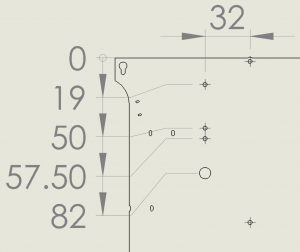
Once the new drive has been assembled, the rear panel must be modified. Four holes should be drilled, in a vertical line 32mm from the centre of the panel. The positions can be marked out using a paper tape as shown below:

Measuring down from the top edge, the following holes must be drilled:
Diameter 3.3mm, distance 19mm
Diameter 3.3mm, distance 50mm
Diameter 3.3mm, distance 57.5mm
Diameter 8mm, distance 82mm
The new extruder drive can now be mounted using the two 12mm cap head screws. The lever can be operated using a screw at least 16mm in length.
With the panel re-fitted to the machine, Fisher is ready for printing again:
 |
 |
All kits shipping from next week will include this update, as well as updated firmware and config files, to be detailed in a later post.

Leave a Reply