
Commissioning
Power on checks
| Before applying 19v to the machine, confirm there is no short in the dc power circuit by measuring the resistance between the screws of the power input screw terminal. There should be very high resistance, or infinite resistance, ie no connection, between these two terminals. | 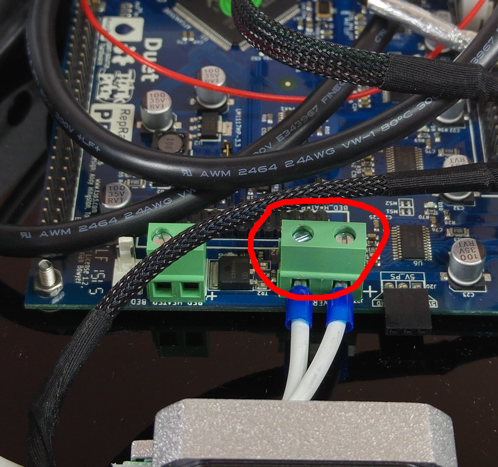 |
| Now connect the power supply to the machine, power it on and make sure the 19v head fan comes on. If it does not, TURN OFF THE PRINTER IMMEDIATELY, and check your wiring. Otherwise, wait a few moments (maximum 20 seconds) and check for overheating of the nozzle. At this stage, the nozzle should remain at room temperature, so if you see smoke emanate from the nozzle, switch the machine off IMMEDIATELY and check your wiring. If the hot end does heat up, you have most probably wired the hot end connector incorrectly, with the hot end heater being connected to the fan output. So rather than the fan being on all the time, the heater is on all the time. |
First connection
| Your Duet is supplied with the microSD card pre-flashed with the default files, and inserted in its socket. If this is not the case, please see the link to the right to download the microSD card image. Then extract and copy to the microSD card, and finally push it into the socket in the Duet. As the Duet is upside down in the machine, the microSD card should be inserted with the contacts face up, until it clicks. | Fisher SD image |
| The folder structure on your microSd card should look like the screenshot. |  |
| Connect ethernet and power to the machine. The machine should connect directly to a router via the ethernet cable. You will then be able to operate the machine from a computer connected to the same network (either WiFi or ethernet). |  |
| Open a web browser and navigate to: http://reprapfisher The web interface will automatically connect if the machine is found. In the case that your network router cannot resolve the machine’s name, you will need to type your machine’s IP address into the address bar.To find the IP address of your machine, click here to run a newtork scan.If this fails, please see the troubleshooting guide here. |
 |
| Navigate to the Settings tab and verify the firmware version, which currently should be 1.16 or later, and a web interface version 1.13 or later. If you have earlier firmware, update your it using RepRapFirmware.bin Flash as per the instructions here. | 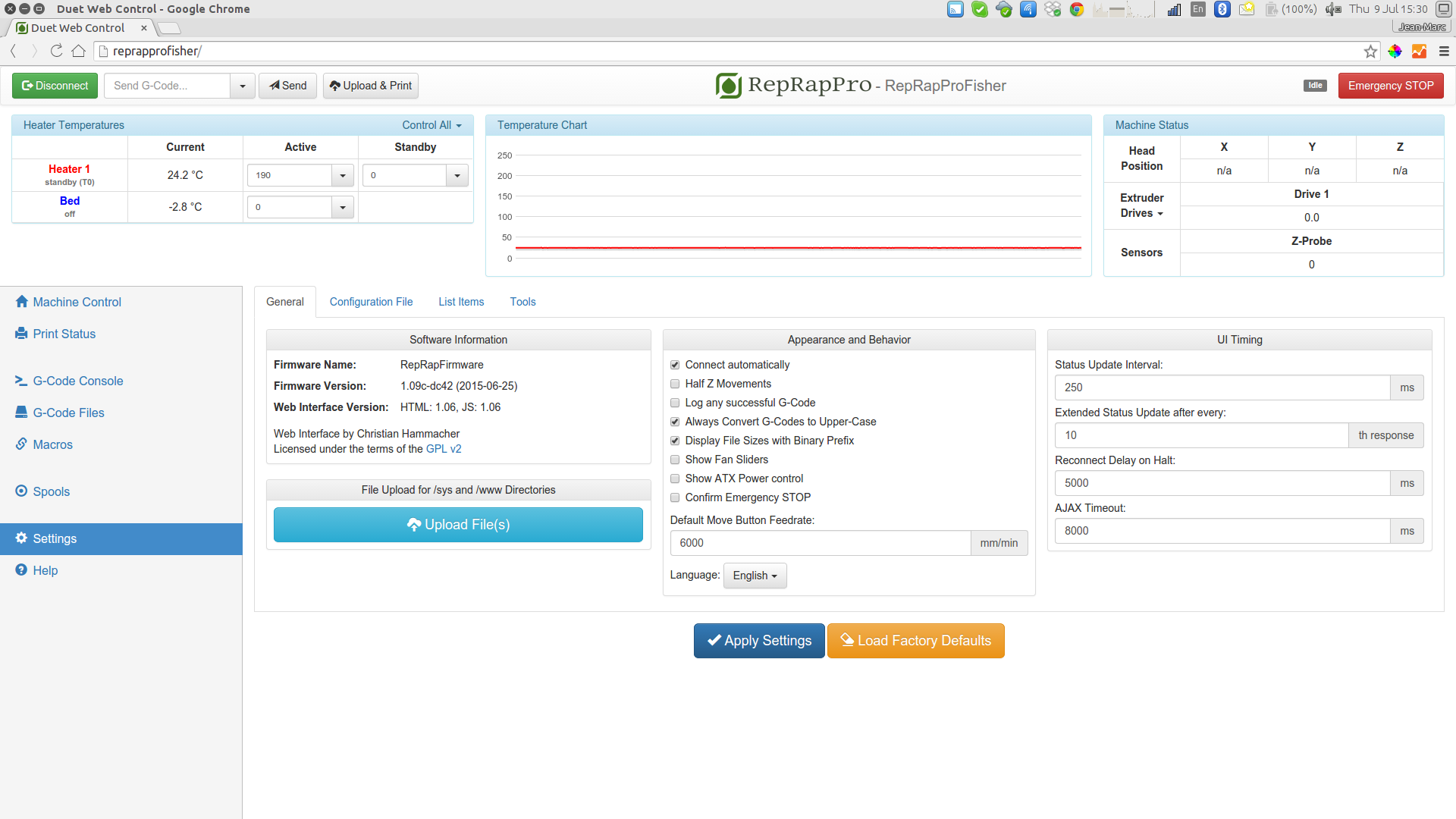 |
| By default, the Duet is set up to get it’s IP address by DHCP (ip address is set to 0.0.0.0 in config.g, to enable this). You can set up the Duet on you network a number of other ways; see here. | |
| If you cannot connect by ethernet, you can run your Fisher from the USB port. Follow the instructions from the general Duet commissioning, which will guide you through setting up communication and connecting. These instructions are for our other, non-Delta printers (Huxley Duo, Mendel 3 and Ormerod), so once connected in ‘Pronterface’, come back and follow the instructions in the following sections. Continue to use the SD Image for Fisher, from the first step above; do not use one of the other SD Images listed in the commissioning instructions, they will not run the Fisher correctly. |
Axis motion
Next test motion of the axes. Navigate to the console tab, then set incremental mode by entering and sending the following code:G91Move all carriages to roughly half way up the bars, then command each axis in turn and confirm an upwards movement of 10mm for each. G1 S2 X10 F500If a carriage moves down, rather than up, power off the printer, and reverse the motor wiring connection for that axis on the Duet. |
 |
End stops
Now confirm the machine registers triggering of the endstops. Navigate to the console tab, then send a command to check the status of the endstops (see picture):M119The response should be: Endstops - X: not stopped, Y: not stopped, Z: not stoppedTrigger the X endstop (the one nearest the first motor which moved in the previous test) by holding down the lever with a finger, and send the command again. The response should be: Endstops - X: at max stop, Y: not stopped, Z: not stoppedRepeat this procedure for the other two endstops, and check that their state changes. |
 |
| If the response is not correct, check your wiring. Check that the endstop wires are connected to the outer two pins of each microswitch, and not the central pin. Check that the correct endstop is connected to the correct place on the Duet (see the wiring diagram). | |
| You can also check the endstops are working visually, by checking the LED lights on the Duet. Lay the Fisher on it’s side, or turn it over completely. You should see the Duet, and 5 LED lights should be lit; the USB LED (this shows the Duet is getting 5V), and the four endstop switches (see the wiring diagram HERE for their location). If any are not lit, check the wiring connections. Press each endstop in turn, and check that the corresponding light goes out on the Duet. Also check the bed probe is functioning, by pressing down on the bed. |
Homing
| Navigate back to the Machine Control tab, and click on the ‘Home All’ button (or send ‘G28’). All axes will move up until they reach the endstops, down a little and back up again slowly, then move rapidly down to rest 4mm above the print surface. |  |
Bed probing
| Monitor the value under Z Probe in the machine status box. The value should be zero. You can also send ‘G31’ to get the current reading from the bed probing. Gently push down then release the bed near each of the mounting points in turn, and confirm the probe value changes to 1000, then returns to zero each time. |  |
Extruder drive
| Push some filament through the slot in the filament guide tube, which should feed it into the extruder drive block. Using the thumbwheel, engage the filament and feed a few centimetres through. Hold the thumbwheel and try to pull the filament back out. If it slips easily, adjust the idler tension using the M4 button head screw. | 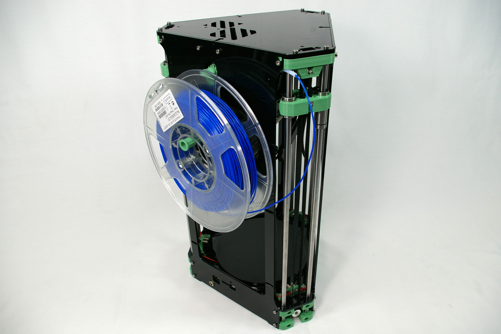 |
Enter a value of zero as the Heater 1 Active temperature. As the nozzle is still at room temperature, cold extrusion prevention must be overriden. Send the following:T0M302 P1Now advance the filament using the jog buttons on the Manual Control tab, until it reaches the top of the heatsink. Once satisfied the extruder drive is working, re-enable cold extrusion prevention using the following command: M302 P0Reset the Active temperature for Heater 1 back to 190C. |
Hot end
| Click on Heater 1 and monitor the temperature rise of the nozzle. | 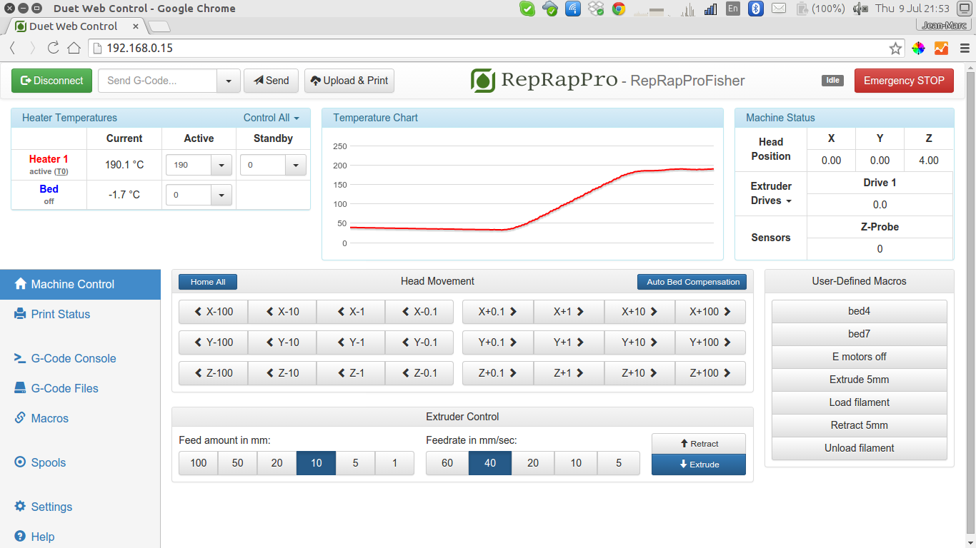 |
The final step is to check extrusion. The extruder drive motor will be enabled, so send the following command to put it into an idle state:M84 E0Using the thumbwheel, feed the filament into the hot end and extrude a couple of centimetres. With a steady feed, the filament should extrude without too much resistance. |
 |
Prepare for printing
Your RepRap Fisher 3D printer is now almost ready for its first print. Check the following before proceeding…
| Filament spool is loaded. Threaded balls are locked and lubricated. Belts are equally tensioned. Top panel is fitted. Bed is in place. |  |
| Back to Bed, top plate and belts | Continue to Printing |