By the end of this section you will have fitted the side panels and connecting rods.
(pic needed)
Side panels
The side panels support the structure of the printer, and keep it square and stable. You will need the following parts:
#
Component
Qty
Type
1302
Front Panel
2
Laser cut
1248
RepRap Logo
2
Printed
242
M3x16mm cap head screw
6
Fastener
185
Microswitch
1
Electronics
133
Cable ties 2mm
1
Electronics
Logo
Peel the protective covering from the panels, then push out the acrylic parts where the printed logo will fit, if they haven’t already fallen out.
Push the logo into position. It will only fit one way around, and from one side of the acrylic panel. This is best achieved by placing the panel face down on a flat, solid surface and gently pushing the logo into place.
Endstop
The endstop is the name given to the microswitch at the end of a linear axis, or carriage. It registers when the carriage comes into contact with it, and gives the axis a known-position.
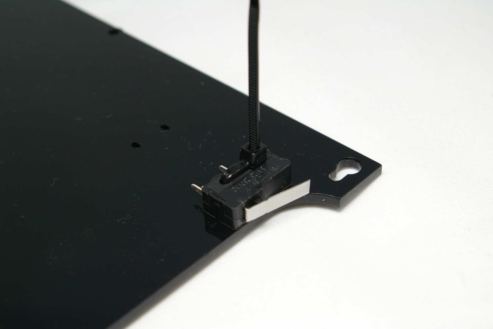
Take one of the panels. The microswitch should fit on the top right of the back of the panel, as shown.
The microswitch is held in place with a cable tie. Note the orientation of the microswitch, with the fulcrum of the lever downwards. Thread the cable tie from the back of the panel, through the bottom hole of the microswitch, through the panel, back in from the front of the panel, and out of the top microswitch hole.
Tighten the cable tie, with the head of the cable tie as close in, and towards the top of the panel. It needs to be here to keep out of the way of the carriage.
Cut off the tail of the cable tie.
Fitting the panels
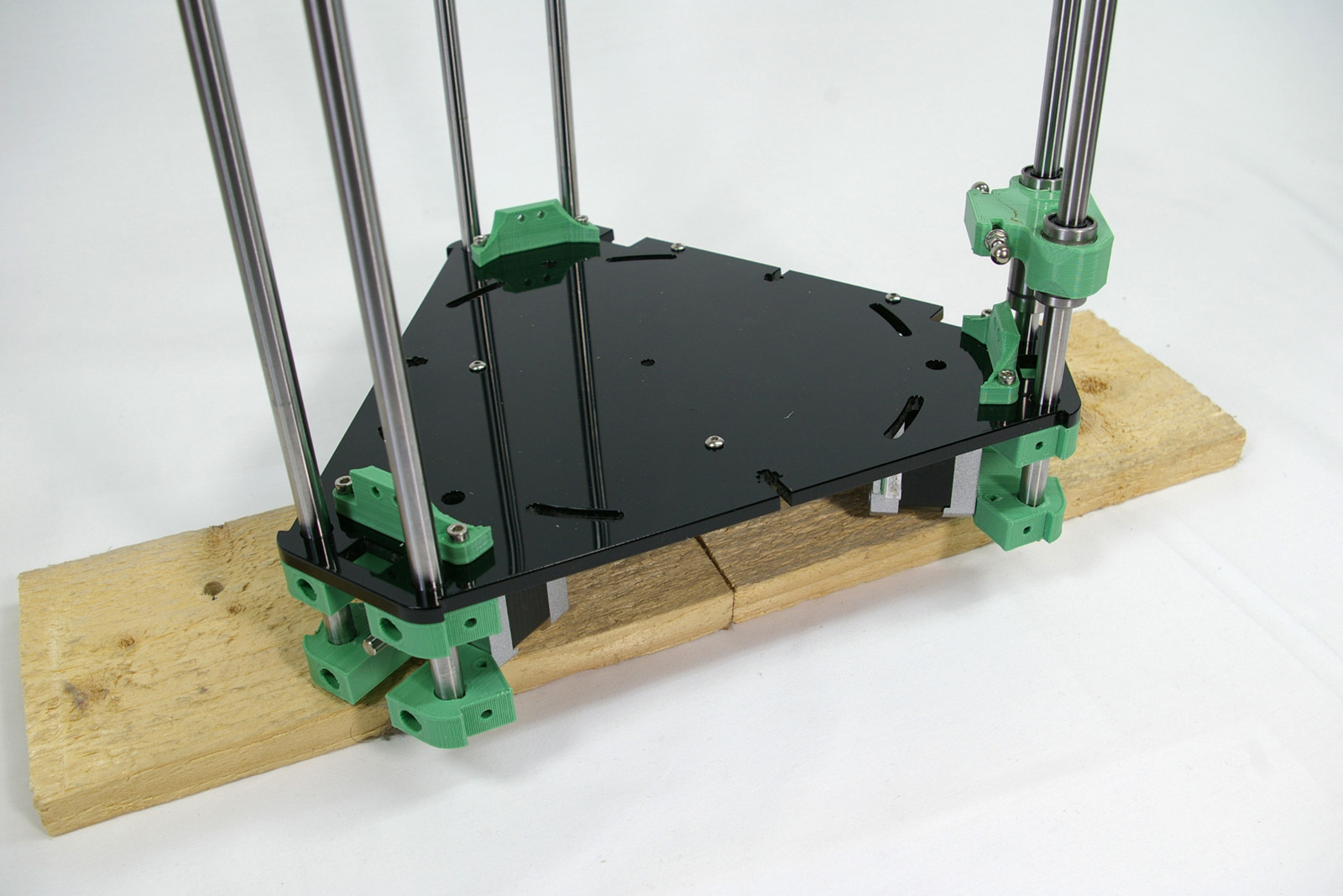
With the Duet electronics facing you, the panel with the endstop needs to go on the left hand side, so the endstop is on the corner away from the Duet electronics on the base. See picture for correct orientation.
Lift the base of the printer up, by resting the motors on something around 10mm thick, eg a piece of wood. The panel is longer than the rods.
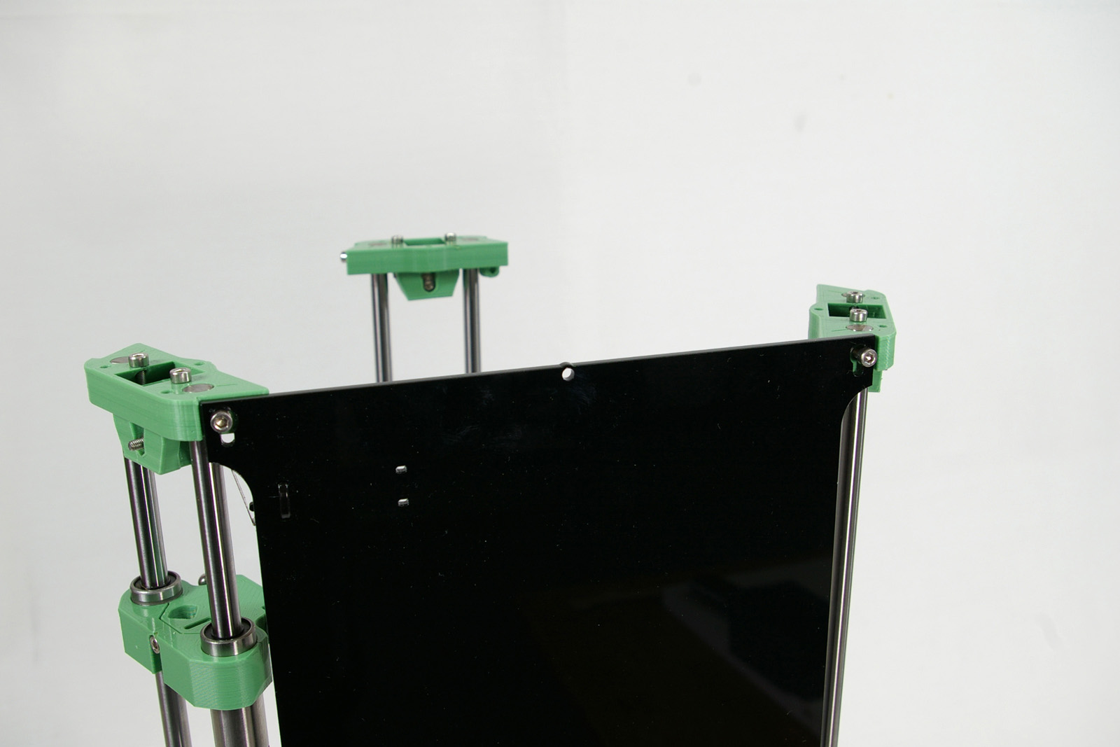
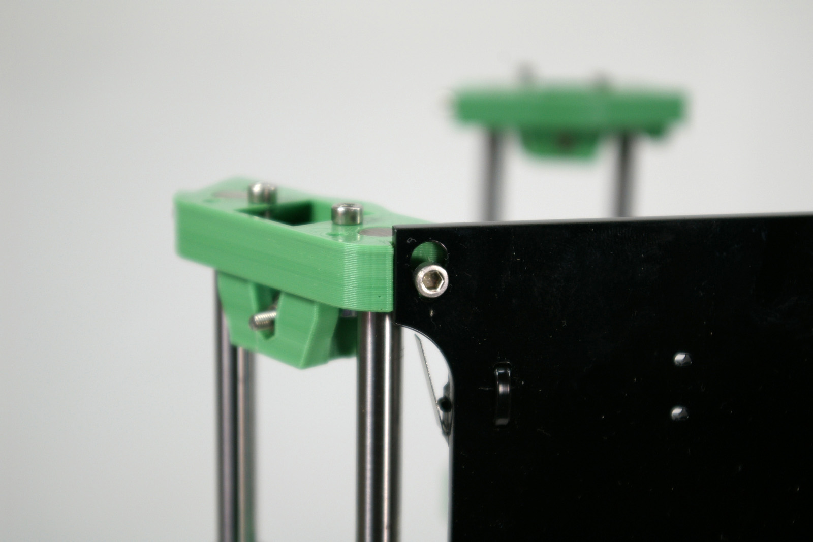
Clip the panel over the cap head screws in the idler bracket at the top of the towers. You may need to slacken off the screws, so they can slide into the slot. Don’t force this; acrylic can be brittle, and may break. Ease it into position.
Line up the four holes in the bottom of the panel with the holes in the motor mounts. Screw in four M3x16mm cap head screws to hold it in place. These self-tap into the motor mounts.
At the top, the cap head screw should move into the slot. It may not be all the way down; don’t worry about this, we will adjust it later.
Repeat the process for the second panel. Note that this does not cover the Duet electronics! The last panel, which covers the electronics, will be put on later.
Again, check that the cap head screws on the idler bracket slot into the top of the panel.
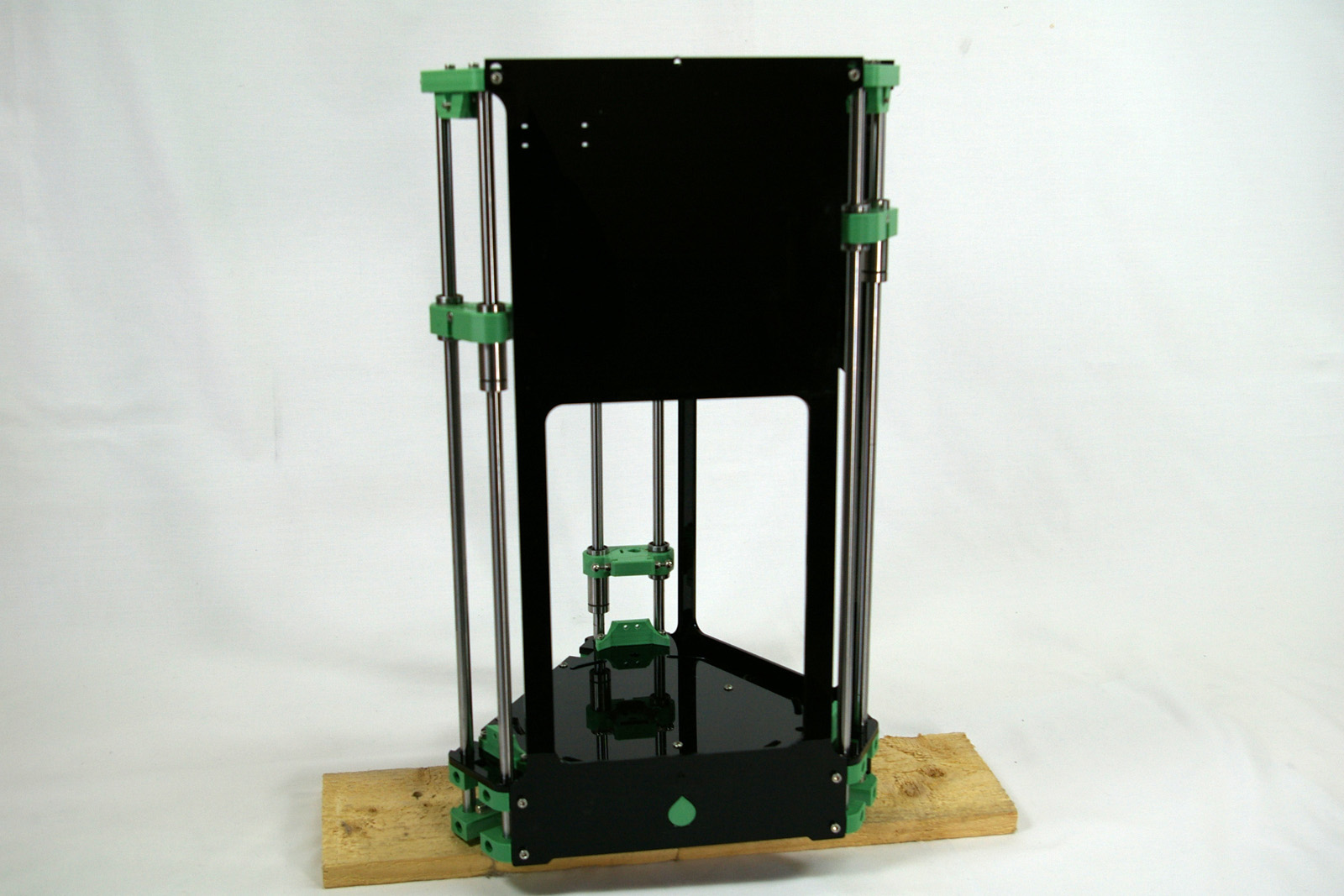
With both in place, your printer will look like this.
Connecting rods
The connecting rods connect the carriage to the effector, translating the movement of the carriage into the movement of the nozzle. You will need the following parts:
#
Component
Qty
Type
1232.1
Rod
2
Laser cut
111
M3x8mm cap head screw
2
Fastener
Assembling a connecting rod
The connecting rods come in a set, and are connected together to prevent breakages during packing and transit. They are held in by a small sprue, and should break out easily.
Remove the protective covering from both sides of the acrylic.
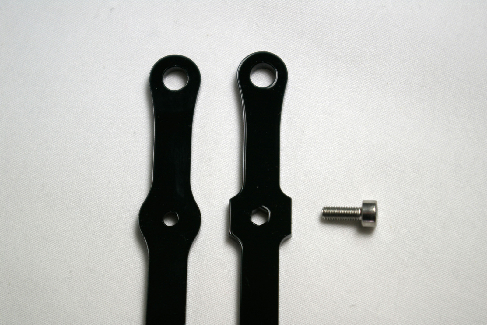
Each rod has a hexagonal and a round hole. The M3x8mm cap head screw should pass through the hexagonal hole, and self-tap into the round hole.
Lasercutting creates an angled cut on the edge of the cut parts. This produces holes with differing diameters on each side of the part. The rods should be paired and arranged such that the angle is mirrored, as shown. Another way to check is that, on the flat faces of the part, one will have a sharper edges than the other. Put the sharper-edged faces together.
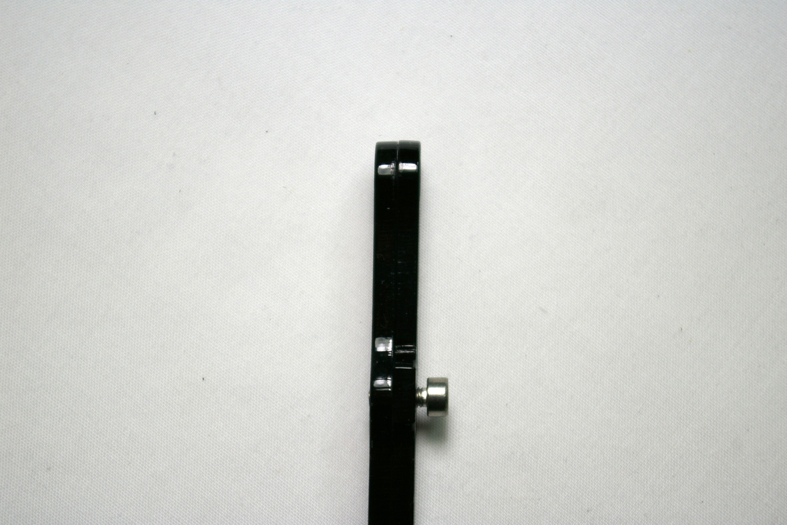
Only screw the M3x8mm cap head screw so it is level with the back of the rod. This will allow it to slip onto the steel ball of the carriage without stressing the acrylic.
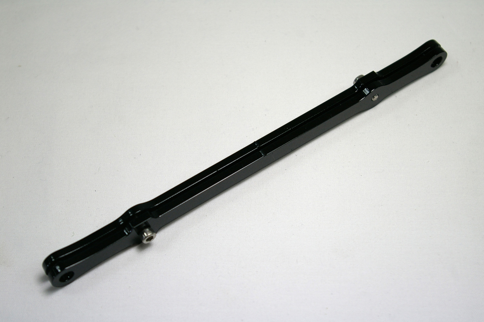
Screw the second M3x8mm cap head screw through the hex hole, and into the round hole, at the other end of the rod. Again, don’t screw it all the way in.
Repeat, and connect to the carriages
Make a further five connecting rod pairs.
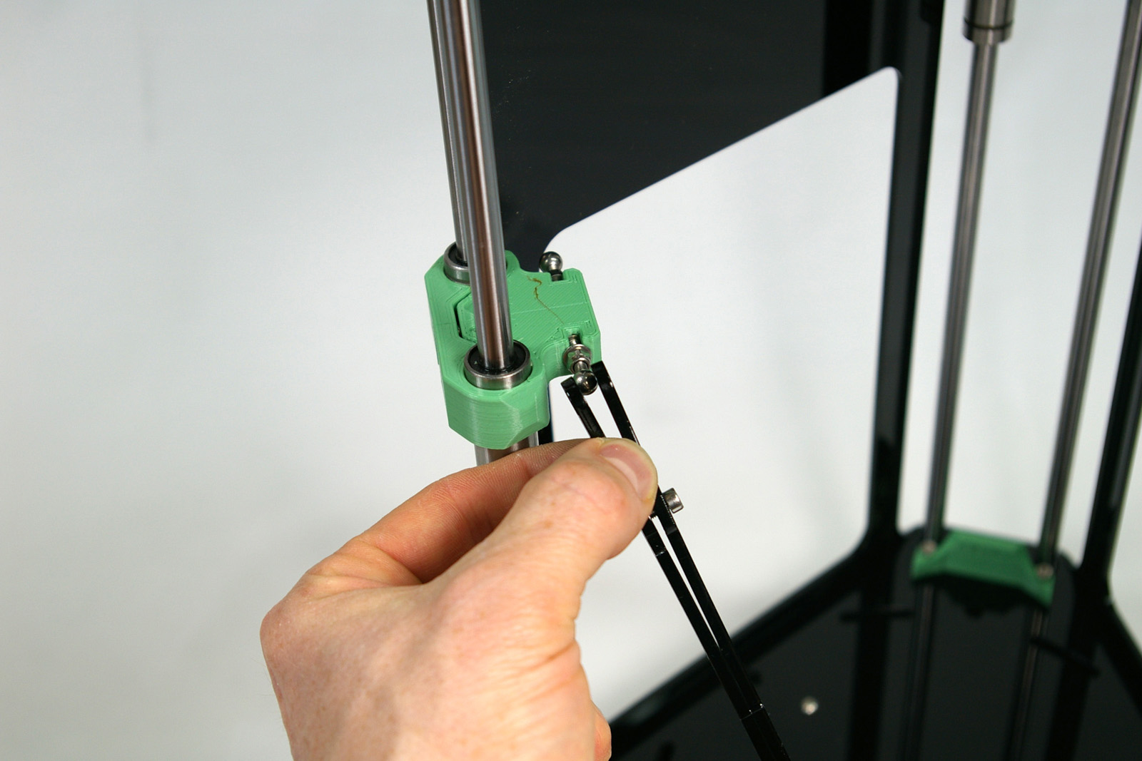
Now connect them to the carriages. Gently spread the rod, and slip it over the ball, so the hole in the rod locates around the ball. Fit it with the screw head facing inwards; this is the easier way around for accessing the screws at the top and bottom.
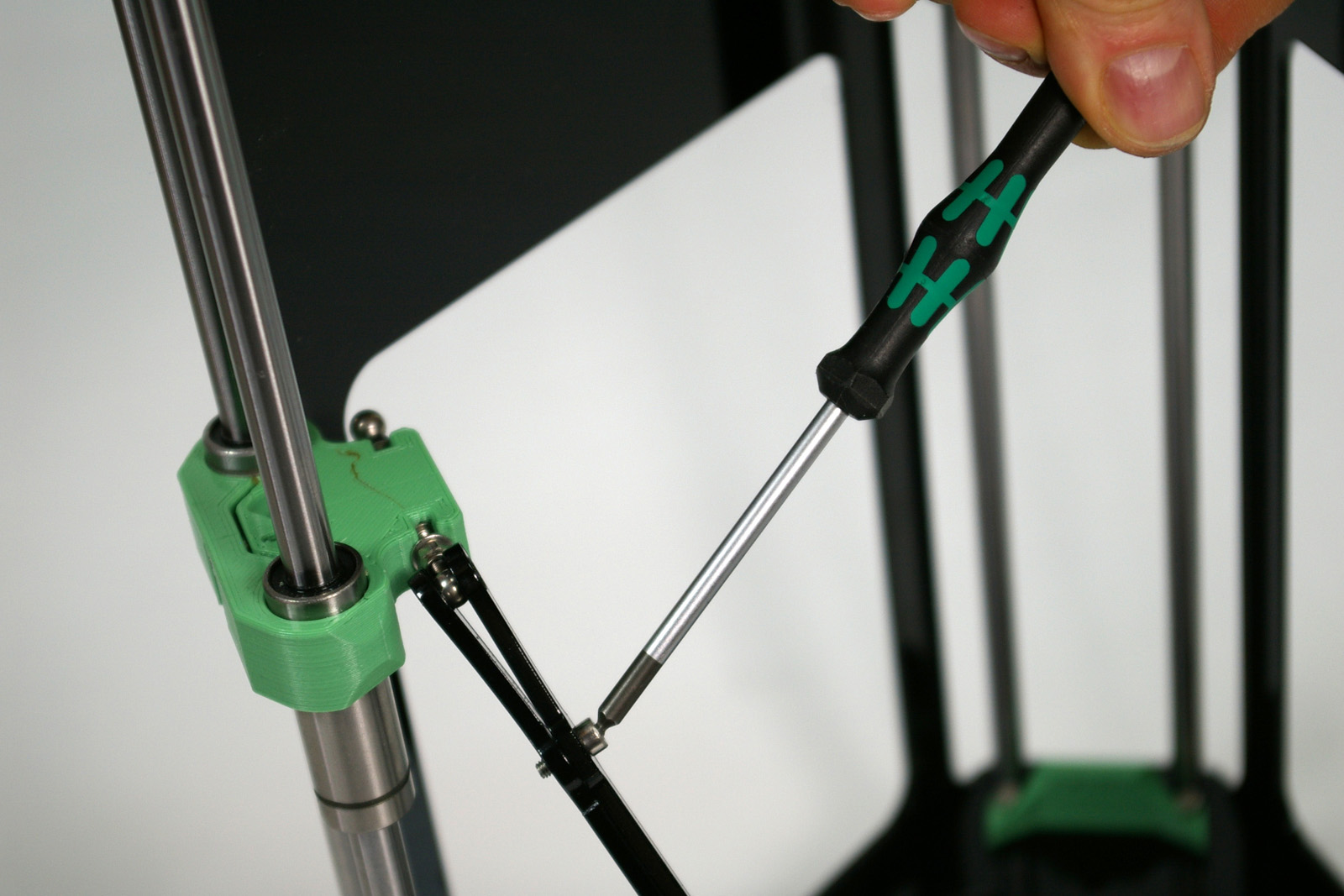
Then tighten the screw until the rod holds the ball. If you wiggle the rod, there should be no play in the joint.