
Duet commissioning
Duet commissioning
There are a number pieces of software used by the RepRap Duet-based printers:
- Arduino IDE (Integrated Development Environment) – used for device drivers, and basic communication (see note and links for downloading later in instructions),
- The RepRap firmware – this controls the hardware functions of the Duet board,
- Pronterface – used for communication and control over the USB connection,
- Google Chrome or Firefox – used for controlling the Duet via the web interface,
- Slic3r – used for translating 3D files into the g-code, which controls the movements of the printer.
| A lot of this software is stored on Github. To download from Github select the branch that you require (unless you are experimenting, this will be “master”), then click the Download ZIP button: |  |
|
IMPORTANT: note about USB 5V power
When using the Duet with 5V power supplied by the USB cable only (i.e. no power supply unit – PSU – power), you may find that the board doesn’t respond correctly. The web interface, SD card reading, IR sensor may all be unreliable. Three different voltages are used on the Duet: 12V for motors, fans and heaters, 5V is used to drive the MOSFET gates, and is converted to 3.3V for most other parts of the board (the ARM processor chip, thermistors, stepper drivers, proximity sensor, SD card, USB, and Ethernet).
It’s possible that your 5V USB power source (usually your computer) doesn’t supply enough voltage, or current, to power the Duet, particularly if you’re working through a low quality USB power supply, an unpowered USB hub, or a laptop with low power USB ports. The Raspberry Pi, which uses a similar ARM chip, also has this problem. Plugging all the other connections in may also drain enough power to cause problems, particularly if there is a short circuit in your wiring.
Check the actual voltage of the 5V and 3.3V power lines. You can measure the 5V on Pin 1 of the expansion header, 3.3V on Pin 3 – these are the pins closest to the heated bed connection, just under the ‘SION’ of ‘EXPANSION’. Anything below 4.5V on the 5V line will make for a marginal 3.3V supply, and could cause a multitude of strange effects on the board.
CAUTION! Take care not to short 5V to 3.3V as you do this, ie touch both pins at the same time! This will short 5V into the main ARM chip, most likely killing it!
The Duet will work correctly when 5V is supplied by the PSU, but don’t plug this in yet. If your USB power is not good enough, then routing the USB from your computer through a powered USB hub will usually work.
Establishing communication with the Duet
This first section should be done with the PSU disconnected from the mains.
The Duet electronics board is based on the Open Source Arduino Due board, with the addition of ethernet, stepper drivers (to control the stepper motors), SD Card slot, temperature sensing and other inputs and outputs needed by a 3D printer. You can use the Arduino IDE (Integrated Development Environment) Software to connect to the Duet on a basic level.
First connection
| BEFORE connecting the Duet to your PC, download and install the Arduino software. Download the latest version from https://www.arduino.cc/en/Main/Software, currently v1.6.6 (as of 1st Dec 2015). Make sure you do this BEFORE connecting the Duet, so the correct device drivers are installed. |  |
| From Arduino IDE v1.6.1 onwards, YOU MUST INSTALL SUPPORT FOR THE DUET, or you will be unable to communicate with it. Again, make sure you do this BEFORE connecting the Duet, so the correct device drivers are installed. Open Arduino IDE, then select ‘Tools’ from the main menu, then ‘Boards Manager…’ |  |
| Click on ‘Arduino SAM Boards (32-bits ARM Cortex-M3)’, then click on ‘Install’ to install the device drivers for the Arduino Due, which support the Duet. |  |
| Connect the USB cable to the Duet, checking that it is correctly orientated. The wider side of the USB plug goes against the Duet PCB. Forcing the plug into the socket the wrong way around will break the socket! |  |
| The plug does not go fully into the socket, as the socket it quite short. Do not try and force it all the way in, or you will break the socket! Also, to remove the plug from the socket, pull it out straight; DO NOT wiggle it side to side, or force, the USB plug from the socket, or you may detach the socket from the Duet. The socket is quite delicate; using excessive force, or knocking it, will break it, rendering the Duet inoperable. Once connected, connect the other end of the USB cable to your computer’s USB socket. |
 |
| Looking at the Duet board, an LED should light up, near the USB connector. See the ‘important note above about 5V USB power’ if it does not. If the Y-axis endstop is fitted (Mendel, Huxley and Ormerod printers), a second LED will light up near this connection on the board. It will be lit if the Y carriage is away from the endstop, and will go out if you move the Y carriage until it touches the microswitch. Try this as a test. For Fisher printers, as there are endstops connected on X,Y, Z and E, four LEDs should light up, one next to each endstop, if the endstops are not triggered. |  |
| Under Windows, your PC should recognise the Duet, and the device drivers should be found by your computer and installed automatically, if necessary. Linux and Apple OS X will create a USB port for the Duet, but don’t usually inform you this has happened. The troubleshooting guide here explains how to check if the operating system can see the Duet. | |
| Open the Arduino IDE and go to Tools->Board menu and select ‘Arduino Due (Native USB Port)’. If this is not available, check that support for ‘Arduino SAM boards’ has been installed. If it is greyed out, make sure the device drivers are loaded, and the Duet board is connected. |  |
| Then go to Tools->Port menu and select the USB port for your Duet. On Windows PCs, this will be a COM[number] port, eg COM7. If you are presented with a list, check which COM port has beed assigned to the Duet, by looking in the Windows Device Manager under the ‘Ports (COM & LPT)’ section; the Duet will be listed as ‘Arduino Due’. |  |
| Then go to Tools->Serial Monitor. This will open a new window. |  |
| From the drop-down menus in the bottom right of the Serial Monitor window, make sure the communication speed is set to‘115200 baud’(bottom right) and that either ‘Newline’ or ‘Both NL & CR’ is selected (next to the speed). | 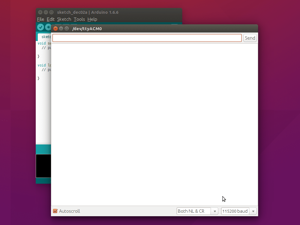 |
Depending on the version of the firmware, you may need to wait for up to 1 minute, then the following should show:RepRapFirmware is up and running.But don’t worry if you don’t see this message; newer firmware sends this very quickly, and is often sent before you can connect! If you close the Serial Monitor, press the reset button on the Duet, then open the Serial Monitor within 2 or 3 seconds, you may see the full message, as shown in the picture. |
 |
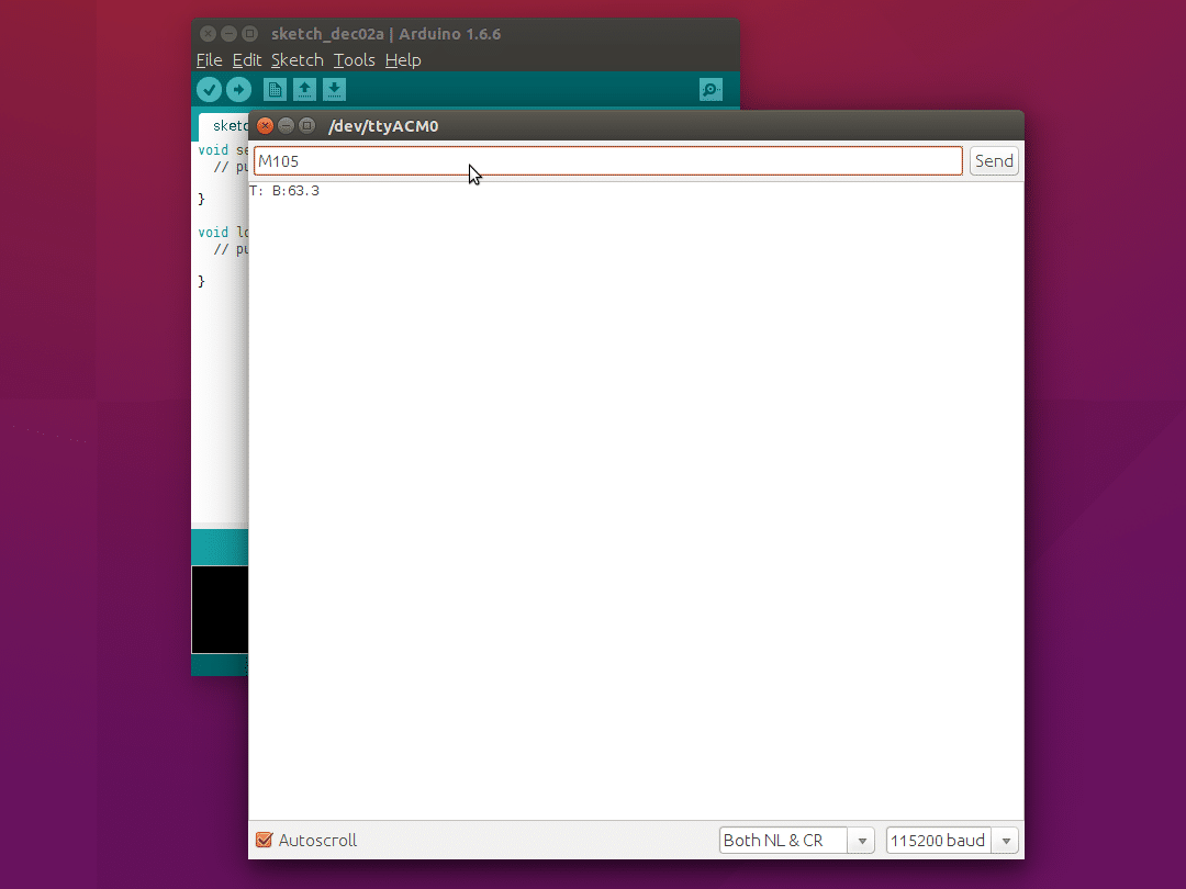
In the top part of the Serial Monitor window, type, then ‘Send’:
M105 This asks the Duet for its temperatures, and you should get a response from the machine, similar to this: T:5.3 B:18.4 or: T: B:18.4 The second response is correct with firmware v0.78c and later. This is because the hot end is a tool, ‘T:’, and has to be defined. This is done in the config.g file, which is on the SD card, which you have not done yet! So don’t worry if you see this, just continue with commissioning. Also, don’t worry about the actual temperatures shown; the configuration has not been set up yet to properly interpret the response from the thermistors. |
 |
What to do if it isn’t working?
If you get no response, close the Serial Monitor window, unplug the Duet, wait 10 seconds, then plug it back in. Check the Arduino settings and try connecting again. Wait for 1 minute after plugging in the USB.
Most problems you may encounter are covered in the ‘Duet software connection problems’ section of the troubleshooting guide here.
If you continue to have problems, contact support.
Update your firmware
Your Duet will have been supplied with firmware flashed in its microcontroller. Now you have established communication with the Duet, it’s a good idea check you have the latest version, and to update the firmware on the Duet if not. We regularly add features and fix bugs, to improve the usability of your printer, so check every month or so.
Recent updates have improved network connectivity, improved USB communication, improved accuracy of thermistors, improved the SD card reading, fixed homing problems, fixed printer stopping problems, and many others. So please, to save yourself potential frustration, update your firmware. All the following instructions assume you have up-to-date firmware.
To check your firmware version, connect to your Duet board via the Arduino IDE Serial Monitor and send the ‘M115’ gcode. The response should be something like:
FIRMWARE_NAME:RepRapFirmware FIRMWARE_VERSION:1.09 ELECTRONICS:Duet (+ Extension) DATE:2015-04-21
Compare the firmware version information from your response to M115, with the file name of the file in this link, which is on our github page. But DO NOT DOWNLOAD THIS FILE DIRECTLY! See here for the full firmware update instructions.
Whenever you update the firmware, ALWAYS update the SD Card with the SD-Image from from the same firmware. You should always keep the SD card files concurrent with the firmware version, or you may get strange behaviour from the printer.
Check SD card Settings
Your printer is supplied with an SD card, and an adapter. Put the SD card in the adapter (if necessary), and into your computer – it should appear on your desktop. The SD Card is used for storing settings, serving the web pages of the web interface, and has some test gcode files for printing.
| Download the RepRap firmware from our Github repository. Do this by going to the page, and clicking the ‘Download ZIP’ button on the right hand side. Extract the ZIP file once downloaded. | |
|
| In the extracted directory is a directory called ‘SD-image’. Open this, and copy the contents to the root of the SD card, so that they are the first thing you see when you open the SD card. |  |
|
| There are a number of directories named ‘sys-[machine name]’, one for each of the different printers we produce. Keep only the one relevant to your machine, e.g. ‘sys-Ormerod-2’, and rename it to ‘sys’. You can delete the others. Your SD-image should look like the picture. |  |
|
Eject the SD card, remove it from the adapter, and put it into the SD card holder on the Duet. It should click in.
Is the SD card being read?
Connect the USB cable to the Duet, and connect to it using the Arduino Serial Monitor, as before. In the top part of the Serial Monitor window, type (without quotes) ‘M503’ and press ‘Send’.
The response shows the config.g file from the sys folder of the SD card, and should be similar to:
; Configuration file for RepRap Ormerod 2
; RepRapPro Ltd
;
; Copy this file to config.g if you have an Ormerod 2
; If you are updating a config.g that you already have you
; may wish to go through it and this file checking what you
; want to keep from your old file.
;
; For G-code definitions, see http://reprap.org/wiki/G-code
;
M111 S0                             ; Debug off
M550 PMy RepRapPro Ormerod 2        ; Machine name (can be anything you like). With DHCP enabled connect to (example) http://reprapproormerod2 (machine name with no spaces).
M551 Preprap                        ; Machine password (currently not used)
M540 P0xBE:0xEF:0xDE:0xAD:0xFE:0xED ; MAC Address
;M552 P0.0.0.0                       ; Un-comment for DHCP
M552 P192.168.1.14                  ; IP address, comment for DHCP
M553 P255.255.255.0                 ; Netmask
M554 P192.168.1.1                   ; Gateway, comment for DHCP
M555 P2                             ; Set output to look like Marlin
G21                                 ; Work in millimetres
G90                                 ; Send absolute corrdinates...
M83                                 ; ...but relative extruder moves
M906 X800 Y1000 Z800 E800           ; Set motor currents (mA)
;M305 P0 R4700                       ; Set the heated bed thermistor series resistor to 4K7
;M305 P1 R4700                       ; Set the hot end thermistor series resistor to 4K7
M569 P0 S0                          ; Set X axis direction
M92 E420                            ; Set extruder steps per mm
M558 P2                             ; Use a modulated Z probe
G31 Z0.8 P600                       ; Set the probe height and threshold (deliberately too high to avoid bed crashes on initial setup)
M556 S75 X0 Y0 Z0                   ; Put your axis compensation here
M201 X500 Y500 Z15 E500             ; Accelerations (mm/s^2)
M203 X15000 Y15000 Z100 E3600       ; Maximum speeds (mm/min)
M566 X200 Y200 Z30 E20              ; Minimum speeds mm/minute
M563 P0 D0 H1                       ; Define tool 0
G10 P0 S-273 R-273                  ; Set tool 0 operating and standby temperatures
;M563 P1 D1 H2                       ; Define tool 1, uncomment if you have a dual colour upgrade
;G10 P1 X19 S-273 R-273              ; Set tool 1 operating and standby temperatures, uncomment if you have a dual colour upgrade
If the SD card is not inserted, or not being correctly read (the error code may be different), you will see:
Can't open 0:/sys/config.g to read from. Error code: 12
Configuration file not found
Check that you have inserted the SD card properly. If you have further problems, there is an SD card troubleshooting guide here.
What is config.g?
The config.g file on the SD card holds the configuration settings for your printer, and is read by the firmware when the printer starts up. It is a ‘g-code’ file; it is a list of ‘g-code‘ commands, that tells the printer what to do. The RepRap G-code reference page has a list of g-codes, their meaning and usage.
You can make changes to config.g, and any other gcode file, by opening and editing it in any text editor. NotePad on Windows, Text Edit on Mac, and Gedit on Ubuntu, can all open them. All gcode files, that the printer uses for configuration and printing, are plain text files, and can be opened and edited in the same way.
Is the SD card being read AT STARTUP?
The easiest way to test if the card is being read at startup is to open the Arduino Serial Monitor, connect, and then send a command, like M105. The correct response should be:
serial: M105
ok T: B:18.4
The important thing is the ‘ok’, which means the M555 P2 (Emulate Marlin USB output) command, which is in the config.g, has run. If you send M105 and get:
T: B:18.4
ie without the command echoed, and no ‘ok’, the config.g has NOT been read at start up. Ignore the actual temperatures that are reported, for the moment.
What to do if it isn’t working?
There is an SD card troubleshooting guide here.
Setting the temperatures correctly
We updated the Duet board with a small change to the thermistor circuit, in mid-October 2014, to make the temperature reporting more accurate at low temperature. At room temperature, older Duet boards can report the hot end temperature with an error of as much as 20C; newer Duets are more accurate at room temperature. Don’t worry – the temperatures are still accurate at their operating temperature on both versions of the board. Duets shipped after this date may or may not have this change, as we (and our distributors) work through our stock of boards and kits.
Identifying if you have a ‘1K’ or ‘4.7K’ Duet PCB
Each thermistor circuit (bed and hot end) is a simple voltage divider, with the thermistor on one side, and a resistor on the other. The part of the thermistor circuit that was changed is the value of the voltage divider resistor. This resistor is either 1k ohm (older Duets) or 4.7k ohm (newer Duets). There are a number of ways to identify if you have an older ‘1K’ or newer ‘4.7K’ Duet PCB.
| Check if there is a sticker on the Ethernet socket on the Duet board. If there is, and it says ‘4.7K’ or’4K7′, as shown, you should have a ‘4.7K’ board. Only boards shipped at the time of the changeover (roughly between mid-October 2014 and December 2014) have this sticker. However, just because it does not have a sticker, does not mean it is a ‘1K’ board! So also check the following… |  |
|
| You can tell from the temperature reported. Make sure the bed thermistor is connected to the Duet, via the heated bed wiring loom. Remove the SD card from the Duet. Plug in the USB cable, and connect to the Duet, using Arduino IDE. Check the temperatures by sending M105. At room temperature (about 20C), the temperature response will be something like ‘T: B:19.6’ for 1K boards, and ‘T: B:54.8’ for 4.7K boards. | With no SD card, temperatures reported: ‘T: B:19.6’ (ie accurately room temperature) = 1K board ‘T: B:54.8’ (ie around 60C) = 4.7K board |
|
| Visually check the value of the resistor on the board – you will need a magnifying glass. Look at the value of the resistors marked R19 and R21, between the main Atmel chip and the Ethernet socket. 1K resistors are marked ‘102’, ‘1001’ or ’01b’. 4.7K resistors are marked ‘472’, ‘4701’ or ’66b’. You can also measure the resistance with a multimeter to check. | 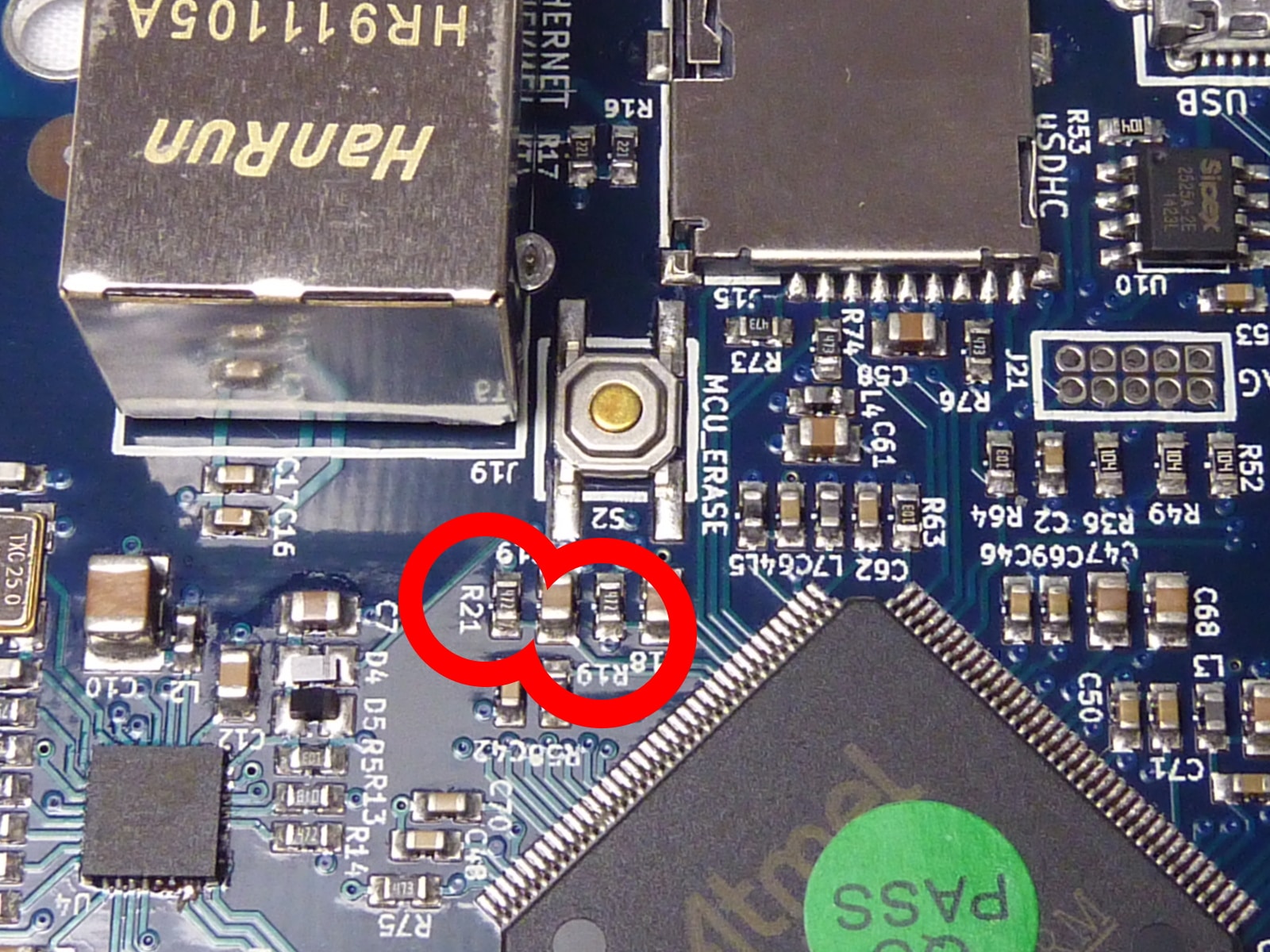 |
|
Setting the temperature for you your board
If you have a ‘1K’ Duet PCB, you should not have to make any changes. If you have a ‘4.7K’ Duet, edit the config.g file. To do this, open RepRapFirmware/SD-Image-[your printer]/sys/config.g that you downloaded earlier, in any text editor. NotePad on Windows, or Text Edit on Mac, can open it. All gcode files, that the printer uses to print, are text files, and can be opened in the same way. Make the following change:
;M305 P0 R4700 ; Set the heated bed thermistor series resistor to 4K7
;M305 P1 R4700 ; Set the hot end thermistor series resistor to 4K7
to:
M305 P0 R4700 ; Set the heated bed thermistor series resistor to 4K7
M305 P1 R4700 ; Set the hot end thermistor series resistor to 4K7
by deleting the semi-colon on the front of the these lines in the config.g (line 20 and 21). Save the edited config.g. Turn off power to the printer (remove the USB cable), and remove the SD card from the printer. Copy the new config.g onto the SD card, into the sys folder, replacing the old version. Replace the SD card in the printer, and turn it back on (reconnect USB). You can also remove the SD card with the power on, but press the reset button on the Duet when you reinsert it, or cycle the power. Any changes that you make to the config.g in future (setting up ethernet, or editing other settings) can be done in the same way.
If you have a 4.7K board, and don’t make this change, your temperatures will report very high at room temperature on both the hot end and heated bed, and will over-read at the target temperature (this is, at least, safer than under-reading!); something like:
T:59.5 B:63.6
If you get negative temperatures, or no temperatures, on either the hot end or heated bed thermistor, it usually means the thermistor is disconnected, or shorting out. Check your thermistor wiring. See the troubleshooting guide here if you continue to have problems.
If you have a 1k Duet PCB, and you are having problems with low temperatures, we can modify the Duet for you. You will need to return the Duet to us, so we can replace the 1K resistors for 4K7 resistors. Contact support to arrange this.
Connect via Pronterface
Pronterface is used to control the printer’s basic functions, via USB. Any version of Pronterface should work with the Duet, though we supply a customised version for our customers.
Installation
Windows
- Download the current version from https://github.com/reprappro/Software (click ‘Download ZIP’ on the right hand side).
- Once downloaded, extract the ZIP file to a sensible location.
- To run Pronterface, double-click the file ‘Duet-[printer type].cmd’, where [printer type] is the printer you have; Fisher, Huxley, Mendel or Ormerod. This will set up Pronterface with the correct bed size and shape, and with the correct buttons. Do not run Win7/Pronterface.exe directly, or it will use it’s default setup.
Mac
Download the pre-compiled version of Pronterface for Mac, and extract the zip file. The Mac version of Pronterface is somewhat limited; USB communication is slow, so do not print directly from Pronterface, always print from the SD card. See the Printing section, HERE. Also, the custom buttons will not show up, as Pronterface uses the default settings. You can simply add any actions you commonly use as a custom button.
Linux
- Download the current version from https://github.com/reprappro/Software (click ‘Download ZIP’ on the right hand side).
- Once downloaded, extract the ZIP file.
- Install the dependencies; see the instructions HERE.
- To run Pronterface, double-click the file ‘Duet-[printer type].sh’, where [printer type] is the printer you have; Fisher, Huxley, Mendel or Ormerod. This will set up Pronterface with the correct bed size and shape, and with the correct buttons. Do not run pronterface/pronterface.py directly, or it will use it’s default setup.
Running Pronterface
Once installed, close the Arduino IDE if it is still open. Only one program can connect via USB at time, either Arduino Serial Monitor ORPronterface. Connect the USB cable to the Duet, then run Pronterface.
Select the USB port that your computer has allocated the Duet in Pronterface’s ‘Port’ box, select a communication speed of 115200, and click the Connect button. As before, you may have to wait for up to a minute. Pronterface will confirm when the printer is online.
Press the GET POS button, and if the machine returns a position of X:0.00 Y:0.00 Z:0.00, your serial communication is functioning correctly.

Check temperatures
Next press “Check Temp” to get an up-to-date reading from the hot end and bed thermistors. You can also turn on the temperature graph by ticking ‘Watch’, which will auto-update the temperatures.

Temperatures are reported in Centigrade. Pronterface reports the temperatures in the bottom left of the window in the form:
T: B:25.0 H0:25.0/-273.0 H1:25.4/-273.0
At startup, ‘T:’ reports no temperature, as no ‘tool’ is selected (hot end heater, thermistor and/or extruder combination). ‘B’ is the heated bed temperature.
‘H’ is for each heater/thermistor. Because heaters/thermistors (‘H’) may be combined to make tools (see next section, ‘understanding Tools’), they are listed separately. H0 is the heated bed temperature, H1 is usually the first hot end. If more heaters are connected, you will see H2…H[x], for the number of heaters you have. This also lets you troubleshoot heater/thermistor reading problems individually.
Each heater ‘H’ has two temperatures, eg H0:25.0/-273.1. The first, 25.0 in this example, is the current temperature. The second, eg -273.1, is the target temperature, ie the temperature that has been set for the heater to reach. -273 effectively means ‘off’.
Check that both the hot end and the heated bed are reporting a sensible current temperature. Look at the first value for each heater ‘H’; they should be reporting around room temperature (it may be a couple of degrees out – the thermistors are designed for accuracy at their operating temperature).
The above picture shows the temperature reported at room temperature. However, the temperatures may report significantly higher or lower than this. The temperature may be reported as:
T: B:-273.1 H0:-273.1/-273.1 H1:-273.1/-273.0
If the first temperature of any ‘H’ is very low (eg -273.1), then there is probably a fault, or no connection, with the thermistor circuit. If it is very high (eg 2000) then there is probably a short circuit in the corresponding thermistor circuit. In either case, find the fault and fix it before you go on. If the temperatures are both reported at around 60C, see the ‘Setting the temperatures correctly’ section above. For more help with temperature problems, see this section in the troubleshooting guide.
If you get a stream of temperatures in the ‘log’ window (the right pane of the Pronterface window), the SD card hasn’t been read at start up (see ‘Is the SD card being read AT STARTUP’ above), and the Duet has not started in ‘Marlin emulation’ mode, which Pronterface needs. Reset the printer, check the SD card is working (try another if it is not), and reconnect Pronterface to the Duet board.
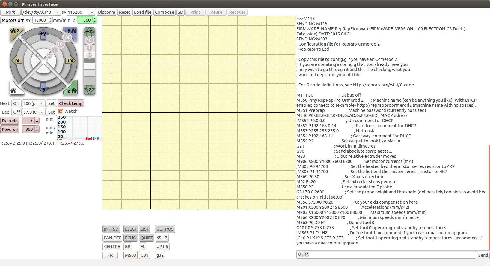
Check the settings by sending ‘M503’ by typing it into the command line in the bottom right hand side of the Pronterface window (or click the ‘M503’ button). The settings will scroll above the command line, in what we call the log window. This establishes that Pronterface is talking correctly to the Duet, and it is responding correctly.
Understanding ‘tools’
Each heater ‘H’ (actually a heater and thermistor combination) and extruder drive ‘D’ are defined in the firmware separately. To make a ‘tool’, the config.g combines any number of heaters (hot ends, usually) and extruder drives. In config.g, M563 defines the tool:
M563 P0 D0 H1 ; Define tool 0
G10 P0 S-273 R-273 ; Set tool 0 operating and standby temperatures
The P field specifies the tool number. Tool numbers can have any positive integer value between 0 and 255. The D field specifies the drive(s) used by the tool. Drive 0 is the first drive in the machine after the movement drives (usually X, Y and Z). The H field specifies the tool’s heaters. Heater 0 is usually the heated bed (if any) so the first hot end heater is usually 1. If there is no H field, the tool has no heaters, eg a syringe drive for extruding paste.
The second command, G10, specifies the operating (S) and standby (R) temperatures. It’s best to leave these off (-273) in config.g, or they will turn on automatically when you turn the machine on, which is not recommended. See later instructions for setting tool temperatures for printing.
Whenever you turn on your printer, or reset the printer, NO TOOL IS ACTIVATED BY DEFAULT (from firmware v1.09 onward). If you try to extrude, you should get a message saying ‘Attempting to extrude with no tool selected.’ To activate the first tool, which is defined as standard as ‘T0’ (tool zero) send:
T0

This will set T0 active, and set the temperature to the operating temperature (as defined by G10). The current tool temperature is reported by the ‘T:’ value, and shown in the graph. You can adjust the temperature again afterwards, manually (see later). You can also turn off the tool by sending any tool command that calls an undefined tool, eg T99. Sending M112 (emergency stop), M0 (stop) or M1 (sleep) also deselects the current active tool. Deselecting the tool will set it to the standby temperature, as defined by G10.
If you have more than one tool defined, sending ‘T1’ will activate that tool, and set T0 to it’s standby temperature, and so on for the number of defined tools. See the multi-materials instructions for more details on setting up multi-material and/or multi-nozzle printers.
Now close Pronterface, and disconnect the USB lead, to turn off the Duet.
Now connect the power supply unit
The PSU will supply the motors and heaters with 12V, while the logic is supplied with 5V.
| Make sure that there is a jumper on the JP10 (ATX_5V_EN) pins (see picture for location of jumper). With no USB lead connected, the only lights to turn on will be the Y axis endstop light (if fitted, it will be lit if the Y carriage is away from the endstop, and will go out if you move the Y carriage until it touches the microswitch) and the lights under the ethernet socket, if an ethernet cable is connected. |  |
|
Testing machine control
Test the heaters
Plug in the USB and run the Pronterface program. Click “Connect” and wait for your RepRap to appear online.
The heated bed and the hot end are the two parts of the printer that may cause damage as they are high-current devices; we check them first, in case there are any problems that have caused a fault.
Tick the ‘Watch’ check box (or ‘monitor’, depending on Pronterface version) to report the temperatures of your heatbed and nozzle. Ensure that the readings are similar to the ambient temperature of the room. If they are not, check connections. Usually, if they are very low (-273), this indicates the thermistors are not connected. If they are very high, this means a short circuit.
Hot end
Send ‘T0’, to activate the first defined tool (firmware v1.04 and later).
Command the nozzle to 100C, by typing ‘100’ in the box next to ‘Heater’, and watch the temperature rise, overshoot slightly, and eventually settle around 100C. When the hot end heater is on, an LED on the Duet PCB, near the heater loom connection, will turn on. Keep an eye on the nozzle during this test. If you see lots of smoke come out of the hot end, turn off the heater and check your wiring. You may have a short circuit or poor connection on the heater wires, or to the heater block, or there may be some contamination around the heater block.
Repeat the test with a target temperature of 200C. The nozzle should reach the target temperature in about 1 minute or less and settle within a couple of degrees of 200C. Some smell of oil burning off is not unusual – it’s the oil from machining the parts – but should dissipate after a minute.
Press ‘Off’ next to ‘Heater’ to turn off the hot end.
Send ‘T99’ to deactivate the tool (firmware v1.04 and later).
Heated bed
Command the heated bed to 45C (warm), by typing ’45’ in the box next to ‘Bed’, and click ‘Set’. When the heated bed is on, an LED on the Duet PCB, near the heated bed connection, will turn on. Verify that the heatbed temperature reading rises and stabilises around 45C, and that the heated bed is actually warm. Again, check connections are not getting hot or smoking. This generally indicates a poor or loose connection; tighten and retest.
The heated bed will heat up much more slowly than the hot end.
Press ‘Off’ next to ‘Bed’ to turn off the heated bed.
Test axis movement
| All 3D printers need an ‘origin’ point for each axis, where X=0 and Y=0. From the ‘front’ of the printer (looking along the Y axis, with the Y motor at the back), this point should be on the front-left of the heated bed. Positive X moves cause the nozzle to move from left to right. Positive Y moves cause the bed to move forward, so the nozzle moves back relative to the bed. If one axis is reversed (incorrectly constructed, or motor wiring incorrect), the nozzle will move in the wrong direction relative to the bed. If both axes go the wrong direction, you may be looking at the ‘back’ of your printer, ie rotated 180 degrees; check the printer orientation. | 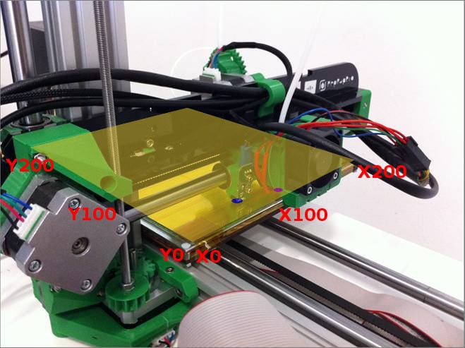 |
|
Now type in the following command in the command line:
G1 X5 F500
in the field below the log window and click Send. The X-carriage should move to 5mm to the right, in the positive direction (X5), at 500mm/min (F500). For Ormerod and Huxley Duo printers, this should be in the direction AWAY from the X motor, and for Mendel 3 it should be TOWARDS the X motor; if it isn’t, check your wiring, as you may have the X axis motor reversed. You MUST turn off the printer to change any motor wires, or you risk destroying the stepper drivers.
Assuming it moved in the correct direction, now type:
G1 X0 F500
and send. The X-motor should move back to wherever it started (X0).
Repeat the above test for the Y axis, replacing the ‘X’ in the above command with ‘Y’. This will move the heated bed, on the Y-carriage. On Ormerod 2, Huxley Duo and Mendel 3, a positive move is AWAY from the Y motor; on Ormerod 1, it is TOWARDS the Y motor.
For Z, make the feedrate 200 mm/minute:
G1 Z5 F200
This will move the Z axis up 5mm. You can also use the ‘jog dial’ on the left hand side of the Pronterface window to move the axes. To turn the motors off, press the ‘Motors off’ button above the jog dial.
Test the proximity sensor
‘Homing’ sends an axis to the end of its travel, and hits an endstop, which gives the printer a reference point. Then it will know where the bed is, relative to the nozzle. The proximity sensor is used to ‘home’ the X and Z axis. For the proximity probe to work correctly, the SD card MUST be working at startup; the ‘M558 P2’ command turns the proximity sensor (also known as the Z Probe) on. You can enter this command separately if the SD card is not in the printer, or did not work at startup.
Move the X and Y axis (by hand – ‘Motors Off’ first – or using the Pronterface command or jog dial) so it’s over the bed, and lift the Z axis so the nozzle is at least 20mm from the bed. To check that the proximity sensor is working correctly, send the following command:
G31
With axis a long way from the bed (say, over 20mm), the response should be a low number, like 20. Put a piece of white paper under the sensor, very close, and send ‘G31’ again. The response this time should be a very high number, like 950. This is the normal range for the sensor, and needs to be correctly working before testing the ‘homing’.
If you do not get numbers in this range, refer to the proximity sensor troubleshooting guide HERE.
Test axis homing
Send a homing command for the Y axis first. Either press ‘Y’ homing button in Pronterface (above the ‘dial’ on the left of the Pronterface window), or use the homing command: for example
G28 Y0
The Z and X drives will move the machine to allow Y to home, then the Y carriage should move towards the Y microswitch and hit it. It then does a little bounce (a move away from the switch and back at much lower speed) to get a more accurate position.
If the wiring for the microswitch is not connected properly the Y carriage will hit the end and try to move against it. This will stop after a few moments. Don’t worry, no damage will be done (though you should avoid doing this regularly as that may loosen some components eventually). Check the wiring for the microswitch; it is possibly disconnected, or connected to the wrong pins on the Duet. There is an LED on the Duet above the Y motor connection. It will normally be on, and will go out when the Y endstop switch is hit. Move the bed to the Y motor end by hand, and check that the LED goes on and off when the Y carriage activates the microswitch.
The X axis endstop is not a microswitch; Ormerod, Huxley Duo and Mendel 3 use the proximity sensor for X homing. This is triggered by the bar that sticks out from the x-motor-bracket. It is important that the X carriage can pass by the electronics housing; this should have been checked earlier in the build. Check that the polarity of the wires connected to the sensor are correct – see the ‘Wiring’ instructions.
| To ensure reliable X homing, you will need to add a piece of paper or adhesive label (like that used on the bed) to the top of the bar for the sensor to work consistently. | 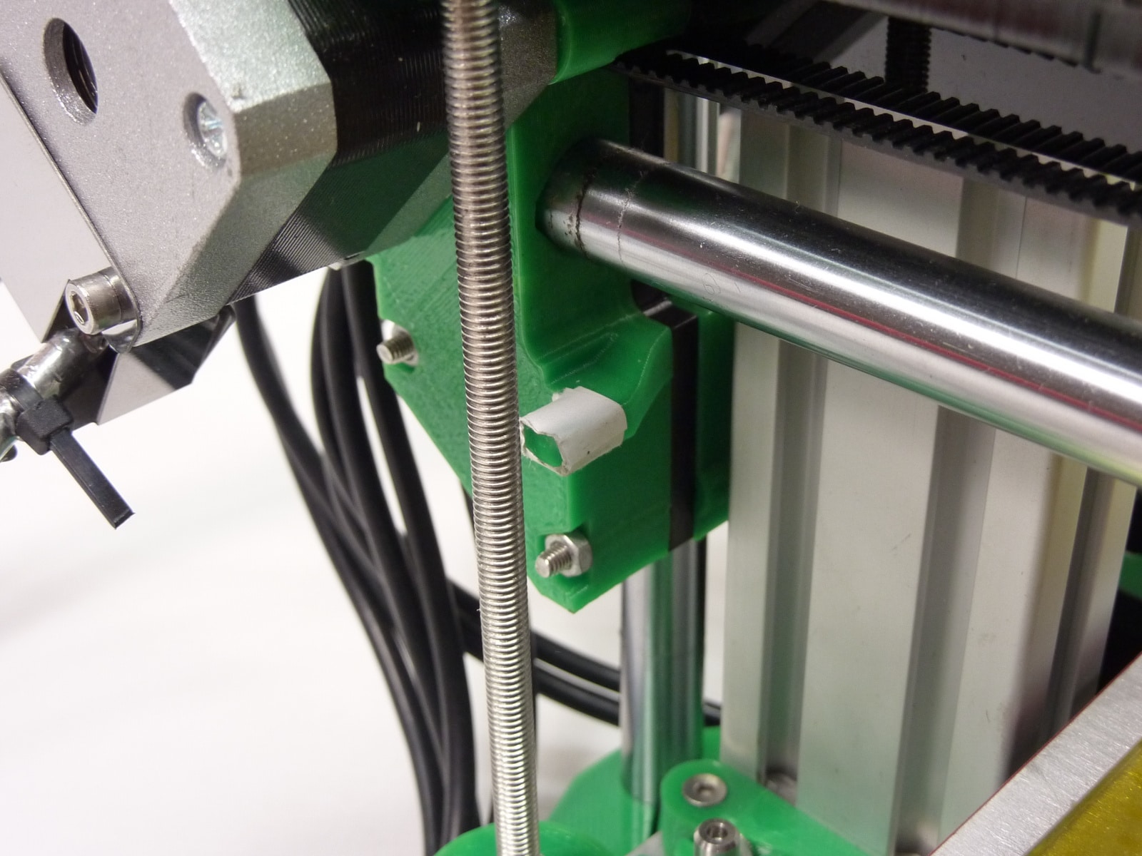 |
|
Press ‘X’ homing button in Pronterface, or use the homing command:
G28 X0
The X carriage should move up a few millimetres, and then move towards the Z axis. It should stop before it hits the end. If this does not work correctly, and it does not stop at the end, and keeps going until it clatters against the X motor, refer to the proximity sensor troubleshooting guide.
Finally, home the Z axis. Again, this uses the proximity sensor. Press the ‘Z’ homing button in Pronterface, or use the homing command:
G28 Z0
The X carriage should move out, to be over a corner with the paper target underneath, then move down and stop. Initially, the nozzle will be some way from the bed; you will correct this by following the ‘Calibration’ instructions.
Test the part cooling fan
Huxley Duo, Mendel 3 and Ormerod 2 (528.5 onwards) printers are fitted with a part cooling fan, in addition to the hot end fan. The part cooling fan is used to help the printing of small part, and bridging and overhanging features, as it cools the extruded filament quickly, setting it in place before the next layer is printed on top. Usually, this fan is controlled by the slicing software, so it turns on after the first couple of layers, and may turn off when not needed, rather than by manual control. It is controllable using M106 ( http://reprap.org/wiki/G-code#M106:_Fan_On ). To test it, send the following:
M106 S255
This should turn the fan on. The ‘Fan LED’ (see wiring diagram) should turn on on the Duet. If the fan doesn’t turn, check your wiring connections. The fan will only work with the correct polarity, with positive voltage on the red wire of the fan. To turn it off, send:
M106 S0
Pronterface – RepRapPro Duet features
Use of the RepRapPro version of Pronterface, with extended features for the Duet, is documented here.
Connect via the web interface
To use the web interface, you need to connect an ethernet cable from the Duet to your ethernet hub, switch or router. The Duet will need to be powered, either by USB or the PSU – it cannot be powered by the Ethernet cable.
The simplest way to connect to your machine is to use DHCP and NetBIOS. DHCP is supported in firmware v1.09 onwards only; for older firmware versions, see “Setting the Duet’s IP address manually”. For DHCP, edit your config.g to the following:
M552 P0.0.0.0                       ; Un-comment for DHCP
;M552 P192.168.1.14                  ; IP address, comment for DHCP
;M553 P255.255.255.0                 ; Netmask, comment for DHCP
;M554 P192.168.1.1                   ; Gateway, comment for DHCP
The semi-colon at the beginning of the line ‘comments out’ (ie the firmware ignores) the command after it. The above will allow your router to allocate an IP address to your printer.
You can also change your printer’s name, by editing the M550 line in config.g:
M550 PMy RepRapPro Ormerod 2
Make sure you leave the ‘P’ before the name, which defines the name.
Connect the ethernet cable to the Duet, and the hub/router/switch at the other end. Then turn on power, via USB or the PSU. The GREEN LED on the ethernet connector should light up, and flicker. The Orange LED is a indicator light for 10base-T connections – most ethernet hubs/routers/switches are 100base-T or gigabit, so that will usually stay switched off.
Open your browser. At the moment, Google Chrome (desktop PC), Firefox (desktop PC), Android Chrome (mobile) and Apple iOS Safari (mobile) are supported. Other browsers may also work, but have not been tested for full compatibility.
If the Duet is set up correctly, you should be presented with a connect screen:

If you have multiple Duets on your network you can open an interface to each one in turn from a new tab in your browser. Keep track of which is which by referring to the name or IP address at the top of each page.
More in-depth use of the web interface is documented here.
Troubleshooting the network connection is covered in the Network troubleshooting guide.