Effector assembly
Goal
| By the end of this section, you will have built the effector. |  |
Effector
The effector carries the hot end, and is moved in three dimensions by the movement of the carriages on the towers. You will need the following parts:
Connecting rod joints
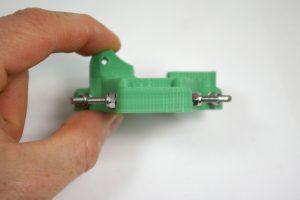
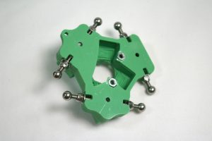
| Take the printed effector, and fit six M3x16mm cap head screws, each secured with an M3 washer and M3 Nylock nut, similar to the carriage. |  |
| Access to the M3x16mm cap head screws is possibly even more difficult than with the carriages. It really helps having a ball-ended Allen key! Tighten them as with the carriage assembly. |  |
| As with the carriages, check that the screws are flat and straight. |  |
| Screw on a 6mm threaded steel ball to each side. As before, make sure the balls are free from swarf inside, and that they are threaded. Fully screw the balls on, then check that the outside measurement of the balls is close (+/- 0.25mm for best accuracy) to 56mm. You can tighten the Nyloc on the screw to pull the ball out a little, if necessary. If too wide, remove the ball and file down the screw a little, then replace the ball and measure. NOTE: Kits supplied after 1st November 2015 have steel balls that are not tapped as deeply as previous versions. The outside measurement with these balls will be a little wider, at around 57mm. |
 |
| The precise distance between the balls is actually not that important. What is important is that the distance between the balls on the carriage (see earlier in the instructions), and those on the effector should be the same, as close as possible. The rods that connect the carriage and effector must be parallel, so that the movement of the effector is always square to the carriage. If the distance between the balls is not the same, the rods will not be parallel, and the movement of the effector and hot end will not be consistent, and you may end up printing parts that are not dimensionally accurate. |
Effector plate
| Turn the effector over, and fit two M3 nuts in the captive holes underneath. |  |
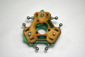
| Take the MDF effector plate, and orientate it so that the holes line up with M3 nuts, and duct holes match the effector. It only fits correctly one way! |  |
| From the top of the effector, put three M3x12mm cap head screws through the central holes, between the connecting rod joint screws. |  |
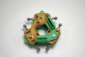
| Turn the effector back over, and fit the MDF effector plate, again making sure of the alignment. Use an M3 washer with M3 nylock nut on two of the screws, as shown. |  |
| Fit the fan duct on the final screw, with an M3 nut. Tighten all three screws to pull the effector together. |  |
| Back to Panels and rods | Continue to Extruder drive |

