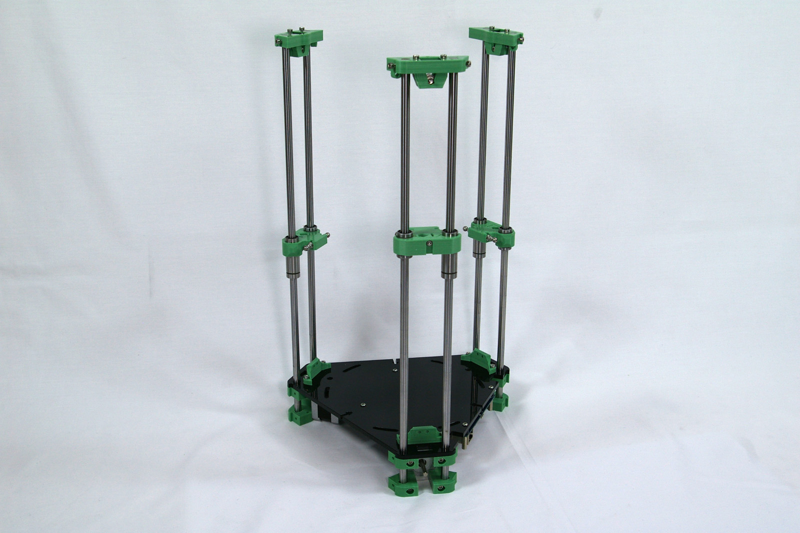
By the end of this section, you will have completed the towers.
Carriage
The carriage runs on the towers, and three of them combine to move the effector, which carries the hot end, that prints parts. You will need the following parts:
#
Component
Qty
Type
1304
Carriage
1
Printed
112
M3x25mm cap head screw
1
Fastener
242
M3x16mm cap head screw
2
Fastener
204
M3 Nylock nut
2
Fastener
212
M3 plain washer
2
Fastener
258
M3 nut
1
Fastener
1191
6mm threaded steel ball
2
Fastener
287
LM8UU linear bearing
1
Hardware
1182
LM8LUU linear bearing
1
Hardware
Connecting rod joints
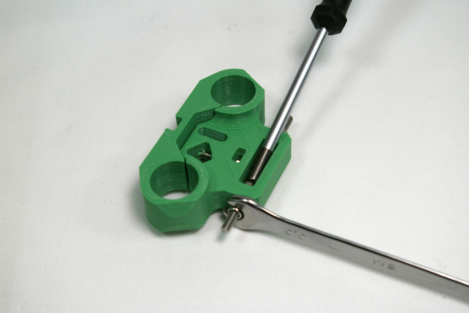
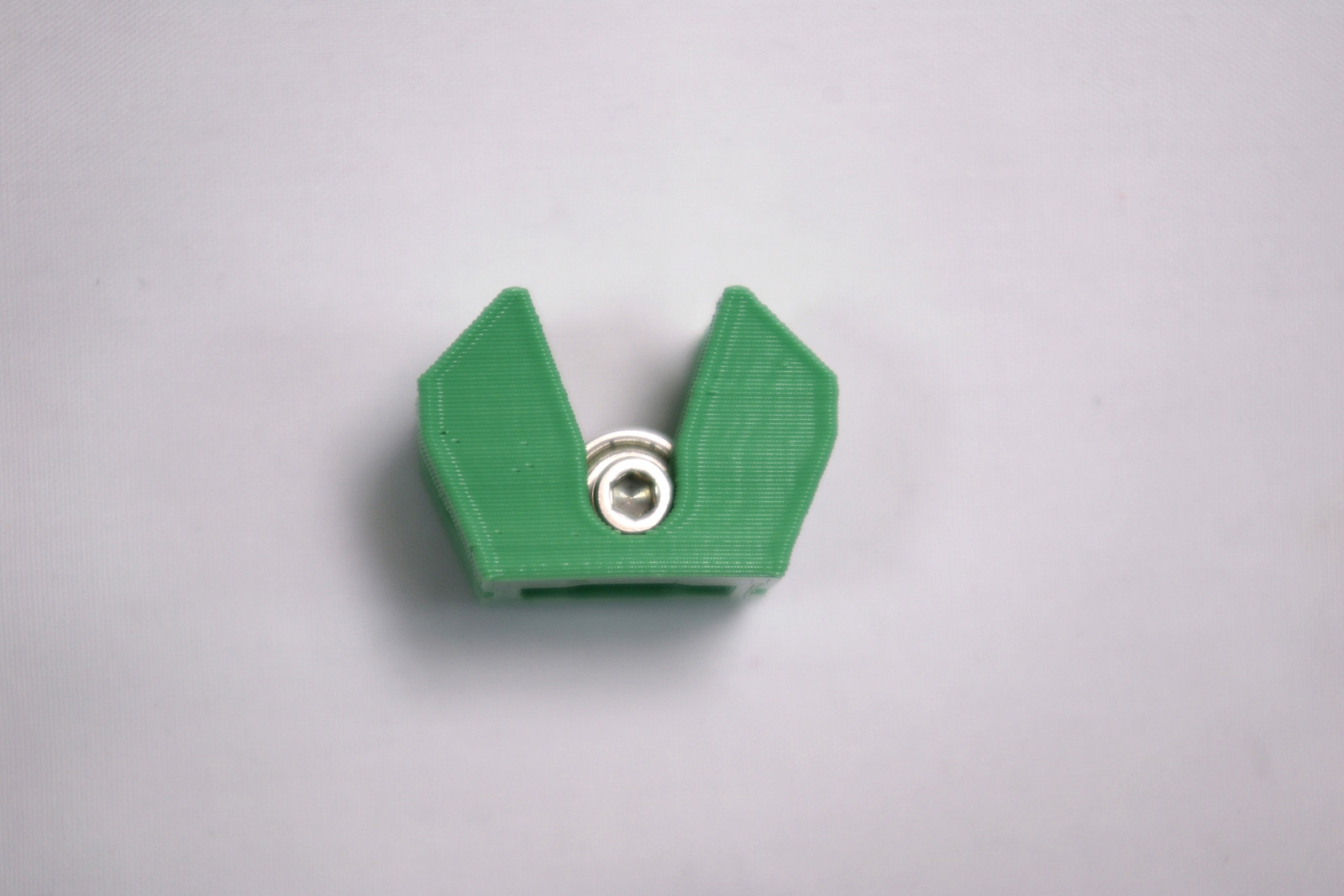
Using an M3x16mm cap head screw, fit this into the carriage as shown. Put an M3 plain washer, then an M3 Nylock nut, to hold it in place.
Place the second M3x16mm cap head screw in the other side, secured with an M3 plain washer and M3 Nylock nut. This screw can be hard to access. It’s very handy to have a ball-ended Allen key, as this can hold the screw at an angle.
But you can do the same thing with a normal Allen key, using the short side. Alternatively, cut down the Allen key, to make it easier to access the cap head screw.
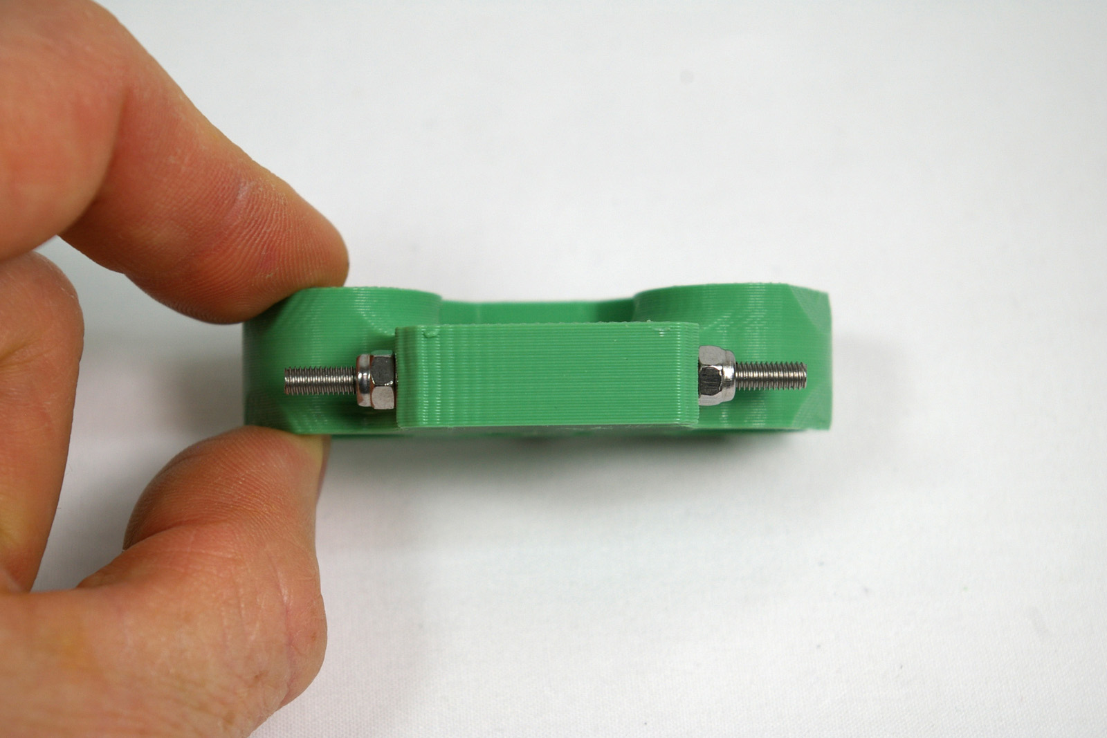
Make sure the screws are straight and level. If they are not, this may distort the print. The nyloc nut and washer should force the screw straight. Tighten them so there is no movement in the screw. This shouldn’t need to be really tight, just pinched up.
Screw on a 6mm threaded steel ball to each side. Before fitting, make sure the balls are free from swarf inside, and that they are threaded (spares are supplied if you have one or two that are not threaded). Fully screw the balls on, then check that the outside measurement of the balls is close (+/- 0.25mm for best accuracy) to 56mm. You can tighten the Nyloc on the screw to pull the ball out a little, if necessary. If too wide, remove the ball and file down the screw a little, then replace the ball and measure. NOTE: Kits supplied after 1st November 2015 have steel balls that are not tapped as deeply as previous versions. The the outside measurement with these balls will be a little wider, at around 57mm.
The precise distance between the balls is actually not that important. What is important is that the distance between the balls on the carriage, and those on the effector (see later in the instructions) should be the same, as close as possible. The rods that connect the carriage and effector must be parallel, so that the movement of the effector is always square to the carriage. If the distance between the balls is not the same, the rods will not be parallel, and the movement of the effector and hot end will not be consistent, and you may end up printing parts that are not dimensionally accurate.
Linear bearings
Drop the M3 plain nut into the nut trap in the centre of the carriage.
Screw in the M3x25mm cap head screw from the front of the part. Don’t tighten it yet.
Slide in the two 8mm linear bearings as shown. Note the orientation.
The short bearing should have equal amounts of it showing above and below the carriage. The long bearing should be set at roughly the same height as the short bearing, on the top. Tighten the M3x25mm cap head screw to hold them in place.
Repeat, then fit
Build two more exactly the same. Before continued use, the balls should be locked onto the threads with an effective thread locking compound (such as Loctite, or we find superglue works very well although one has to be careful, and quick, screwing the ball on). If you prefer to leave this until the machine is built, in case you need to go back and fix build errors, then leave until after the commissioning stage (which includes a reminder).
Slide each carriage onto a tower, with the balls inwards, and the longest bearing on the right, downwards, as shown.
NOTE: Take special care when sliding the bearings over the ends of the rods to ensure the axes of the rods and the bearings are aligned. It is possible to cause irreparable damage to the bearings by sliding them over the rod ends whilst misaligned, causing some of the balls to fall out.
Idler bracket assembly
The idler bracket is at the top of the tower, and provide the bearing around which the belt will go, which drives the carriage. You will need the following parts:
#
Component
Qty
Type
1285
Idler bracket
1
Printed
1243.1
Idler
1
Printed
242
M3x16mm cap head screw
5
Fastener
258
M3 nut
5
Fastener
212
M3 plain washer
2
Fastener
279
623 bearing
2
Hardware
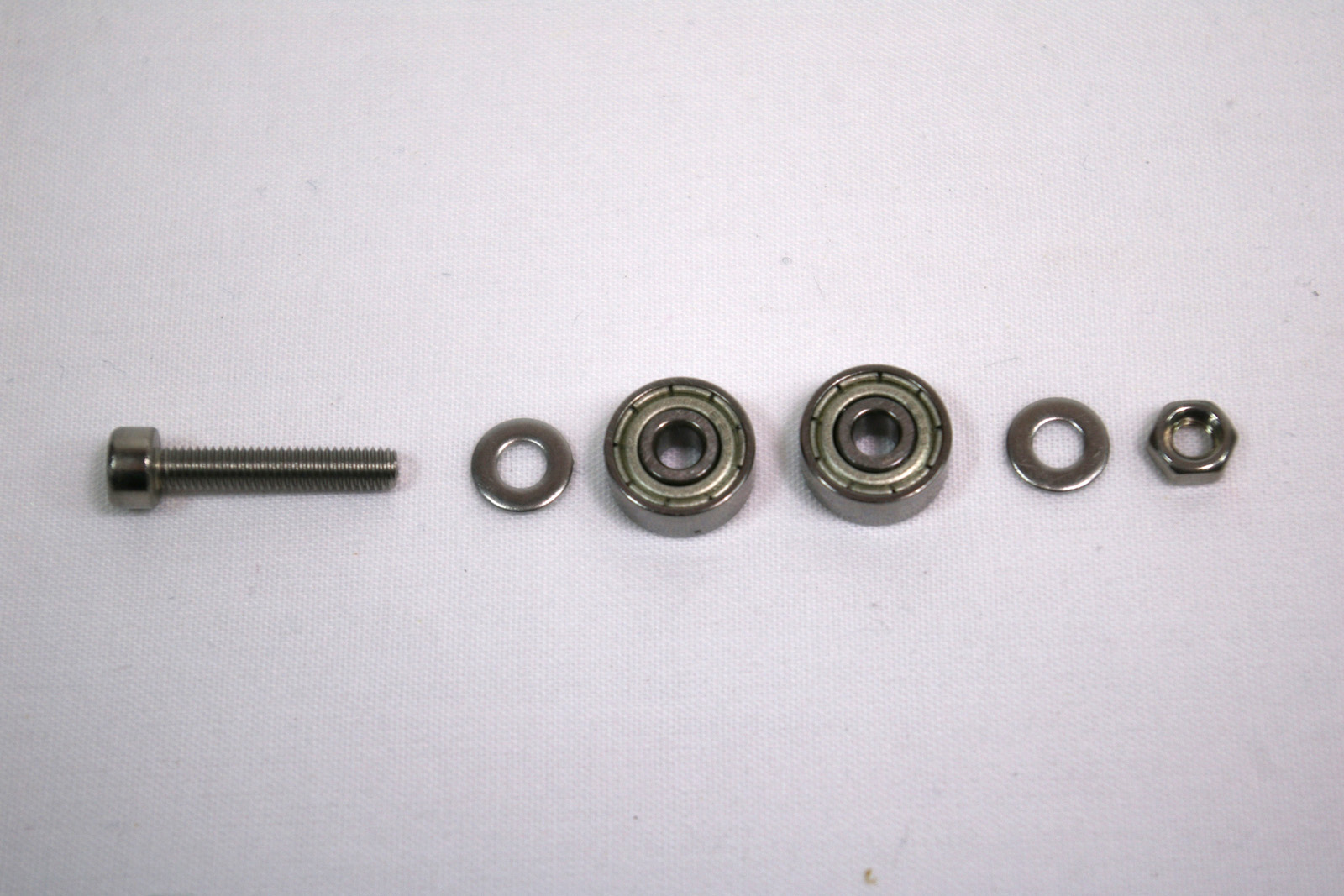
Idler
Assemble the idler bearing in this order: M3x16mm cap head screw, M3 plain washer, 2 x 623 bearing, M3 plain washer, M3 nut.
Tighten this up, but check that the 623 bearings can rotate freely. If they stick, try turning the washer around. These tend to have a rounded side and a more flat side; put the rounded side towards the bearing.
Push the idler bearing assembly into the printed idler part. The two side are different, with a seat for the M3 nut on one side, and for the screw head on the other.
Make sure the idler bearing assembly is seated fully in, and the bearings are level with the idler printed part.
Idler bracket
Push two M3x16mm cap head screws through the idler bracket, as shown.
Push an M3 nut into each recess in the idler printed part. Screw the idler up into the recess in the idler bracket. This will later be used to tension the drive belts, so may be left loose at this stage.
Drop an M3 nut into the nut trap recess, and screw in the last two M3x16mm cap head screws as shown. These will hold the top of the side panels, so again, leave these loose at this stage.
Repeat, then fit, again
Build two more idler brackets, exactly like the first.
Fit them, one on each tower, as shown. The smooth rod should be flush with the surface of the idler bracket.